 |
Forward Controls By Max Verver ...Back...|...The Gallery...|...Hondachopper.com's Index... |
|
Forward Controls By Max Verver ...Back...|...The Gallery...|...Hondachopper.com's Index... |
|
and to Max Verver, biker bro from the Netherlands for contributing his design. |
|
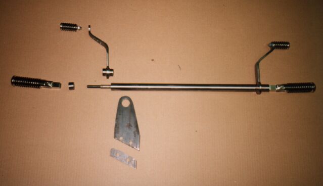
| Here's a guide on how to make a set of forward control for your Honda chopper. I suggest that you first need to read through this a couple of times and it'll become clear how these are made. The left side of the forward controls are unassembled so you can see their components. The right side is completed so you can see what the finished project will look like. | |
 |
|
|
The main rod is basically a straight bar (axle steel), 25 mm thick, with the ends turned down to 12 mm over a length of 30 mm. The main rod is then turned down about 50 mm to 10 mm thick with an M10 thread on it to accept a 15 mm long locking.....eehhhh.."thing" (can't think of an English word for that right now) made out of the same bar with M10 on the inside, with a small securing bolt in it to lock the "thing" to the bar. The final 35 mm thread is to screw the foot peg into. I used Zodiac foot pegs that would fold up so it would be easier in the turns. On the 30 mm long turned down piece of bar is a machined piece of bar of 30 mm ( x 25 mm outside diameter) with a 16 mm hole drilled right through. In that hole I machined a boss ( like a bearing ), made from what we call " Messing" ( self-lubricant metal), with a 2 mm thick sleeve on one side ( and a lose ring on the other ) to fit tightly over the 12 mm bar. |
| I turned two rings of
about 8 mm thick with a 30 mm hole and welded that to the 30 mm piece of
bar, so I could later weld the levers to them. You have to do it that way
around, with the levers already on they will not run in your milling machine
!!! ( Actually I welded them on before making the " Messing" bearing ).
I then cut two pieces of metal to make the brake and gear lever, bent them to fit my seating position and welded them to the rings. On the gear lever side I also welded a piece of metal with a 8 mm hole in it, to the bottom of the ring to attach the gearchangebar. |
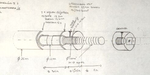
Here's the rough drawing which I
started with.
|
 |
The bigger pieces of metal
carry the forward control bar through the 25 mm holes ( secured with 4
more securing rings, not in the picture, made from a thicker piece of bar
with a 30 mm hole in them, secured by a small bolt ). It bolts to the pieces
of metal welded to the frame with four 8 mm bolts.
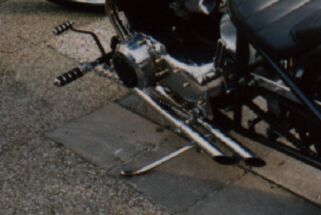
I cut of the original gear lever and drilled a 8 mm hole in it, and bought a bar of 8 mm Stainless Steel, on which I machined M8 thread on both sides. A ball joint with a 8 mm hole in them on each side and the gear lever worked !! |
| Take care: keep the length
of the cut down original gear lever and the length on the bottom of the
forward control equal, so the gear changing will be short and quick. the
longer one of the stems, the more weak it will feel .
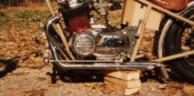
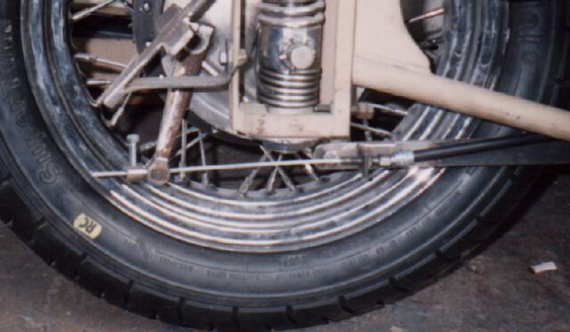
On the brake side, I drilled some holes in the lever and started looking for a suitable cable. After spending an hour in a clutch and brake shop, I finally found a cable with an eyelet on one end ( has a kind of ring on the end of the cable with a 8 mm hole). I can attach that to the lever by means of a piece of SS bar with 8 mm thread on both sides, with a ball joint on the lever side and a sort of " fork " on the other end. You can get the idea in the picture below: |
 |
| Next, I soldered the cable at the required length so it wouldn't split when I cut it. For the brake side, I machined a small cylinder, with a hole drilled trough it to suit the cable. The cylinder is stepped, so one piece fits in the drum brake lever and the other piece sticks out. I drilled two small holes in the piece that sticks out, made thread in them and put 2 small bolts in them ( after final installation with LocTite ) to secure the cable. |
 |
|
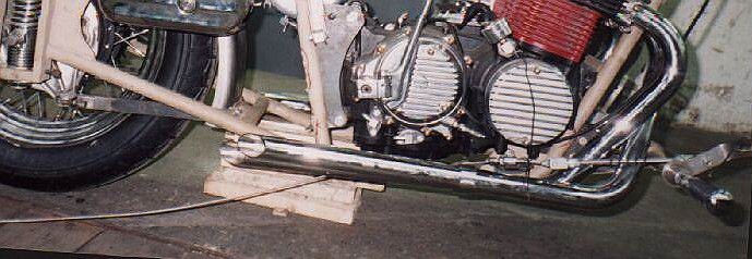
| I slid the inner cable
through the outer cable and put that along the frame. On the rear brake
torque arm I made a small bracket to hold the outer cable and I did the
same at the front of the frame, where the cable starts. That's also
visible in the picture above.
Can't think of anything else to tell you. I made the thing more than 10 years ago and it was not difficult. It works perfectly. No need to adjust anything once it is in place, except for the initial stretching of the rear brake cable, but that's only a matter of sliding the cable a little further through the cylinder on the end of the cable. Good luck ChopperHedz. |
 |
|
|
|
![]()